
Some time ago I built the Bottlehead Crack amplifier and reviewed both the build process and the resulting sound. After thoroughly enjoying the Crack for over a year, I decided it was time to enjoy the next step up in the Bottlehead range for both a challenge and a new step towards audio nirvana. The next step in the Bottlehead range is called the Single Ended eXperimenter kit (or S.E.X. for short). It’s a different design to the Crack as the S.E.X. uses output transformers to work with a wide range of headphones. (The Crack is an output transformerless (OTL) design which will only work effectively with high impedance headphones.)
The S.E.X. has a lot more wires than the Crack (partly due to having two output transformers) so it’s a slightly more complex build, but it’s still fairly simple point-to-point wiring with no circuit boards or finicky micro components.
The Kit
 What arrived at my door was a moderately sized box containing a couple of plastic bags of components and wires, 4 pieces of wood which make the base, 5 cardboard-wrapped power components (transformers, etc.), an aluminium chassis plate, a list of parts, and a CD containing the manual in PDF form.
At first glance I actually thought the S.E.X. was going to take only a tiny bit longer than the Crack… oops!
Customisation
Having built the Crack completely stock in all ways except for staining the wooden base, I decided I would express myself a little more in this amp. I love the Art Deco period and I thought that style would match the vintage tubeyness of the S.E.X.
To achieve the vintage look I decided to paint some of the visible metal parts and my fiancée convinced me to anodise (rather than paint) the aluminium chassis plate – thanks Lisa!
Painting
Painting the metal elements of the S.E.X. required a lot of careful preparation. The top of the main power transformer and the brackets on the plate chokes (the things on either side of the transformer) needed thorough sanding to remove the varnish that they are coated with during production. The plate choke brackets had a lot more varnish than the transformer bell, but both were tricky to sand and took multiple attempts to get right.
I was using an etch primer to ensure a good finish on the metal parts, but my first priming attempts didn’t go well. Despite fairly thorough sanding, there were small patches of varnish left on the metal and the varnish reacted with the etch primer to create a crinkled look that would have really messed with the final paint finish. Having failed once, I stripped all parts bake to 100% bare metal before starting again.
 In this image you can see the metal parts all sanded and masked for painting. This image was actually before the first, failed attempt. You can see a dark patch on the top left corner of the front piece (the transformer bell) which is some of the left-over varnish that I failed to fully remove.
It’s worth adding at this time that masking the plastic parts on the plate chokes is VERY difficult. There are a lot of small sections that are tricky to mask and I found that using lots of small pieces of tape was more effective in the cramped spots than large pieces of tape.
Once correctly masked and sanded, the metal parts were relatively easy to prime and spray. The only other issues I had were keeping dust out of the fresh paint job and paint quality issues. I dealt with the dust by lightly sanding the blemished coat and lightly respraying. The paint issue was solved by changing paint brands and actually led to a fortuitous change of colour from off-white to cream which better suited my desired colour scheme.
Anodising
 I was worried that the anodising was going to be expensive and possibly time consuming. It turned out to be neither once I found the right provider.
After a few calls I came across Riga Crafts who were located fairly close to me here in Melbourne and were able to work with a small scale, single-piece project like mine. I delivered to them a simple aluminium plate (as seen to the left) and received back a strangely  mottled looking brassy coloured plate. I had ordered the bronze colour, but expected something much more brown, much less yellow, and much more consistent in colour. Before you think Riga did a bad job, please read on because their work was wonderful!
I don’t fully understand why, but for some reason, the colour on the chassis plate became uniform over the next few days and went more brown than yellow (as I had wanted). The finished product perfectly matched the sample Jimmy at Riga had showed me and was a perfect match for my design idea.
Assembly
 So far everything I’ve discussed I did on my own, but I actually bought the kit with 2 friends (1 kit each) and we agreed to build them together.
The first stage of building was a night of assembly where we screwed all of the components to the chassis plate in preparation for a separate wiring and soldering adventure.
The assembly stage of the S.E.X. is very straight forward, much like with the Crack. It simply involves clicking into place the various plastic power parts, screwing on some terminal strips and installing the volume control, headphone jack and tube sockets. All straight forward except for the tube sockets which were a little fiddly to get centred and well secured.
At this stage, I also had to make sure to create a good earth point on my anodised chassis. The anodising process creates an inert layer on the surface of the aluminium which means it no longer conducts electricity. That’s a slight problem when you want to create an earth on the chassis, but it’s easily solved by just taking a file or a piece of sandpaper to the chassis plate around the earthing screw hole (see silver screw to the right of the black box on the chassis near the far left corner).
After just a few relaxed hours, the underside of our chassis plates looked something like the image to the right.
We could have installed the plate chokes and output transformers at this stage, but this involved a tiny bit of soldering so we left it to be done at the same time as the other wiring and soldering.
Wiring & Soldering
I mentioned earlier that there are more wires to work with in the S.E.X. compared to the Crack. We allowed a day and an evening to do the wiring and soldering, but we should have split it over 2 days. It’s not hard as such, but it IS time consuming so please allow plenty of time and some breaks to ensure an enjoyable build process if you decide to buy and make the S.E.X.

To do the work, we setup a table with a sheet of thick cardboard to catch any solder drips and prevent damage to the table we were using. This turned out to be a great move because we were able to fold up the cardboard at the end of the night and easily dispose of all the little wire and insulation off-cuts we’d created. I can highly recommend this approach!
The first step in the wiring of the S.E.X. was to install the plate chokes and power transformers. At this time we also had to decide on the impedance we were wiring the S.E.X. for. You can choose from 4, 8, 16 or 32 ohm loads and should make the decision based on the speakers you will drive with the amp (if you will ever use speakers), or on the power vs noise ratio you are after. Lower impedance wiring means a quieter amp, but with less power so it all depends on your usage. We all chose 8 ohm wiring because it suits most common bookshelf / desktop speakers and also will work with most headphones, except the most power hungry orthodynamics out there. You can also buy an impedance switch from Bottlehead which allows you to easily change the impedance setting later buy simply switching the unit off, lifting the chassis plate and throwing a switch. It’s a great idea for those wanting all options, but not necessary in my case.
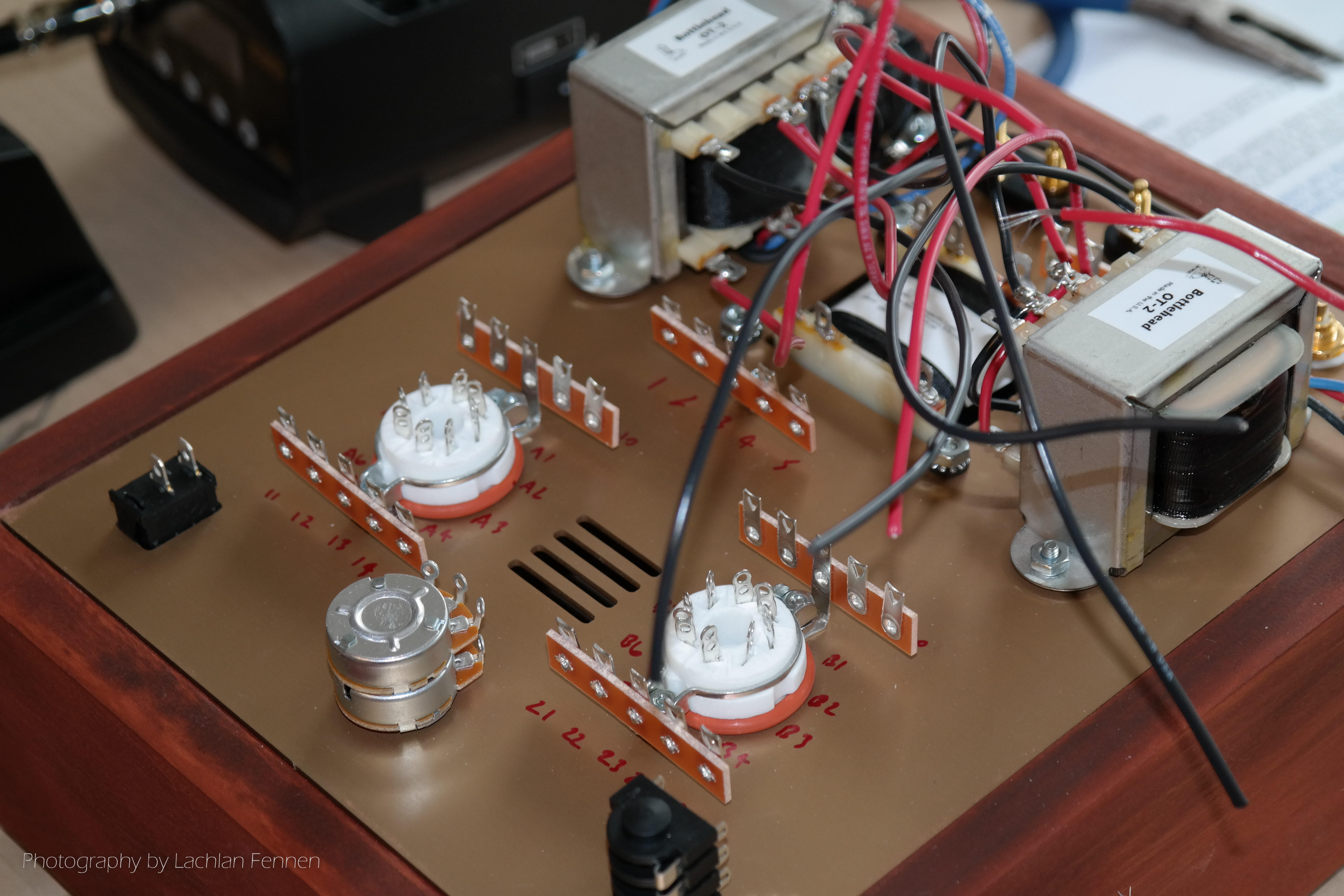 Once the chokes and transformers were all installed we were ready for the hardcore wiring and soldering. You can see the numbers written on the chassis plate in the image to the left and the wiring process is as simple as following Bottlehead’s brilliant and clear instructions. For each wire or terminal, there are numbered terminals to connect each end to. The biggest challenges in the wiring process are confirming the right parts are used the right ways, especially for the directional components like capacitors and diodes, and also soldering in cramped spaces as the circuit nears completion.
 In all cases, the instructions are extremely clear and every written instruction is accompanied by a clear picture of the connections being made. The instructions specify the correct orientation of directional parts and even remind you to double-check before soldering. With patience, care and attention there’s really nowhere to go wrong.
Hook-Up Wire
Unlike the Crack, which used single core wires throughout, the S.E.X. uses a mixture of single core and multi-core wire. This makes the build slightly more fiddly because stripping and preparing the multi-core shielded wire takes a little more care and time, but it has it’s benefits because the shielding prevents noise creeping into the wire itself takes up less space in a circuit where real estate is in relatively high demand.
Wire Lengths and Paths
 Because the finished product becomes an organised mess of wires and components (see left), it’s important to focus on tidiness as you progress the build. Even though mine’s not bad, if I had my time again there are some things I would do differently to ensure a much neater finished product.
Although the measurements in the instruction manual never once left us short of cable, it sometimes seemed to be too much cable. Thinking back this might be because we took a direct path between the 2 connection terminals when the better path may have been around other things to keep them clear. In short, if I were to build the S.E.X. again I would manually check and plan the path and length for each wire before I cut it.
 As you can see in the image to the right, the S.E.X. can look neat and tidy if you get it right. That image is from the Bottlehead website and was no doubt built buy one of their wizards, but it’s definitely a level of finish to aim for.
The main thing at this stage is to be wary of soldering in close proximity. It can be easy to accidentally touch a wire or the side of a capacitor (for example) with the soldering iron and melt the insulation or destroy the component so take care and think about each step before you do it. I can very close to destroying one of the capacitors and I think we all disfigured some insulation here and there.
Those Bloody Rectifiers!
 Perhaps the trickiest part of the build happens quite early when you’re building what will become the power supply for the tube heaters. It involves the use of some rectifiers which have really thick, stiff leads and all go in a tight spot between the power transformer and a terminal strip.
In the image to the left, you might be able to see some small black cylinders in the bottom third of the image. Those are the rectifiers and you can see from this shot that they’re all smashed in together in a very cramped spot. This is made harder by the fact that you have to pre-bend the very stiff leads prior to installing so it’s pretty fiddly.
What makes it worse is that the rectifiers are directional so you have to get them oriented correctly. Getting this wrong (as one of us did) is a real pain because desoldering and changing them is very tricky due to the cramped space and stiff leads. My tip? Care, attention and patience!
Testing
Once all of the wiring and soldering is completed you’re almost ready to test. I say almost because it’s worth giving the whole circuit a once-over before testing because if you’ve missed any solder joints (we all missed at least one) or done a poor job of a joint it’s much quicker to find it visually now before you try to troubleshoot strange readings during your test. A good solder joint should have ample solder, but not too much, and should be shiny, not dull.
The instructions for testing are as clear as everything else in the manual so it’s fairly straightforward. Stage 1 is an impedance test without the power connected so you can’t hurt yourself at this stage. After checking the resistance across a range of terminals you can either troubleshoot or continue.
Stage 2 involves power and therefore extra care. Once again the process is straightforward, but there is now the risk of touching a high voltage source so patience and care are key.
If, like us, you find strange readings at this stage, the first thing to check (again) is your solder joints. A partial solder joint can create very strange symptoms in your circuit. It’s also very important to take care with your circuit even after unplugging the power. We had a scary moment where one of the guys touched a component that should have been safe because the power cord was unplugged, but the capacitors hadn’t discharged their power due to a dodgy solder joint. The result was a few hundred volts through the hand and a very unpleasant experience so please be careful!
Building the Base
The wooden bases are very simple, but allow for lots of customisation. You can build it early or wait till the end – it doesn’t really matter.
 I found that building the base is as simple as gluing the pieces together with PVA craft glue, but we discovered (the hard way) that some glues work better than other. One of the guys had a craft glue which is extremely strong and actually made it impossible to fix any assembly errors.
I found the PVA craft / hobby glue to be a really nice compromise between bond strength and flexibility. It gives you time to adjust the positioning of the pieces of timber before it dries too solid and can be pulled apart if absolutely necessary. My approach was to put a zig-zag of glue along the edge of one piece of the base and then sandwich it together with the other piece. While the glue was still wet, I gently slid the pieces of wood until the edges all lined up to a nice flush finish. Because the wood is all pre-cut with a ridge for the chassis plate to rest on it’s easy to identify which parts go together. Once again it’s a case of patience and care.
Stains & Finishes
The beauty of the natural wood base is that you can make it look however you want. On both my kits I’ve chosen to stain and varnish, but you could also paint the timber, oil it, or just sand it lightly and keep it natural – it’s all up to you.
For the record, staining is a fairly simple process of wiping or brushing the stain onto the timber and allowing it to dry. You can also do things like wiping off any excess or lightly sanding to create an uneven / aged look on your stain. Once stained, you can varnish or oil the wood to complete the look of the stain. I guess you could leave it just stained, but my experience with the two stains I’ve tried is that it didn’t look particularly good until varnished.
Conclusion
 Once the build is all done and you’ve tested the circuit you’re ready for listening and feeling the massive sense of satisfaction that comes from hearing your handiwork sing. Be prepared for a fantastic experience because this amp is a beauty!
I was unfortunate enough to have a faulty tube with major hum and noise, but the lovely folks at Bottlehead were quick to offer a replacement and I found a local supplier to buy some from in the meantime so I didn’t have any downtime (and will have spares for the future).
I’ll share a full review of the amp’s sound in the coming weeks so please subscribe if you’re interested in more!